Euro Plus Chicken Cage
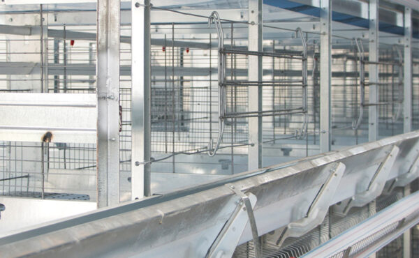
Cage Mesh
The dividing wires are designed to allow light and air circulation, and the 7º inclined base wires allow eggs to easily reach the egg collection belt. The dividing wires at the back of the cage mesh are divided by the dividing wires. The cage lids operate horizontally, allowing them to be easily opened and closed. The cage meshes are 62.5 x 60 cm (9 hen capacity). Two pieces of 3 mm thick twisted reinforcing wire are installed under the egg meshes.
Irrigation System
There are two nipples on the "PVC" pipes that run from the middle section of the cage partition side plates across the cage. The "V" water discharge basin immediately below prevents water from reaching the fertilizer belt. Water from the network is sent to the "PVC" pipes at appropriate pressure via a reservoir. There is one reservoir on each floor. Our irrigation system uses long-lasting connection elements with increased leak-proofing capabilities.
Feeding System
Our trolley feeding system, an ideal feeding method preferred in the poultry industry, ensures that feed reaches the feed troughs evenly and hygienically with its designed feed distribution apparatus. It also prevents overflow and feed waste by ensuring safe and rapid distribution. Our feeding system's mechanism operates fully automatically and semi-automatically using rope-driven motors with power ranging from 0.75 to 2 hp. Our feed buckets are assembled from galvanized sheet metal with bolts and rivets. Feed is perfectly distributed from the silos to the feed carts via spiral augers passing through pipes with diameters of 107 and 127 mm, varying according to cage capacity. Our feeders are designed to ensure that evenly mixed feed reaches each level without overflowing. The freezers located at the beginning of our feeding system are controlled by control switches. At the end of the system, there are control connections and the electrical panel for these connections.
Manure Discharge System
Manure is transported via a POLYPROPYLENE (plastic) manure belt, which is located under each floor and conveys the manure to the discharge belt, which extends along the cage. The movement in the transport process is provided by geared motors. Scrapers located on each floor ensure that the manure is delivered flawlessly to the manure discharge conveyor located at the end of the chicken coop. A protective curtain is placed at the back of the cage to prevent contamination from manure splashes. The conveyor rollers on the heads are coated with special rubber. 1st class material is used in the control panels used in the manure conveying system.
Platform
Our cage is designed to be divided into two for ease of use. The platform is constructed using 2.50 mm thick expanded metal. The platform aims to make it easier to control the cage cells and the animals. A platform is built between the blocks and the rear areas.
Digging Area
The scratching mat is made of hard plastic and measures 35x35 cm. The hard plastic scratching mat is irritating to the hen and prevents her from laying eggs in this area. The scratching mat has round holes to prevent manure from accumulating. A gizzard box sits on top of the scratching mat. The hen satisfies her natural urge to scratch by digging in the stones and sand from the gizzard box.
Roosting Area
There is 15 cm of perching space per chicken. It is designed to allow chickens to perch comfortably. It aims to provide evenly distributed pressure under the chickens' feet and allow them to rest on a safe perching area.
Curtained Nest
To prevent any disturbance to the hens while they are laying eggs, there are two nests in each cell. The nest is covered with a flexible curtain.
Nail File
There is a nail file with embossed abrasive features on the inside of the breastplate for filing the chicken's nails. There are 4 nail files in each cage compartment.
Lattice Construction
Strut Thickness: 2.00 mm
Partition Wire Thickness: Ø 2.00 mm
Feed Chute Thickness: 0.70 mm
Breastplate Thickness: 0.60 mm
Feeder Leg Thickness: 1.50 mm
Side Sheets (Band Bearings): 1.00 mm
Rail Sheets: 2.00 mm
Cage Heads: 3.00 mm
Base Wires: Ø 2.00 mm
Cover Wires: Ø 5.00 mm
Partition Wires: Ø 2.00 – 4.00 mm
Upper Wires: Ø 2.00 mm